The technical third no one asked for, but was built anyways:
A cute rocket-shaped ‘card’ counting the number of times light travels to the Moon and back, from Earth.
The final completed ‘card’.
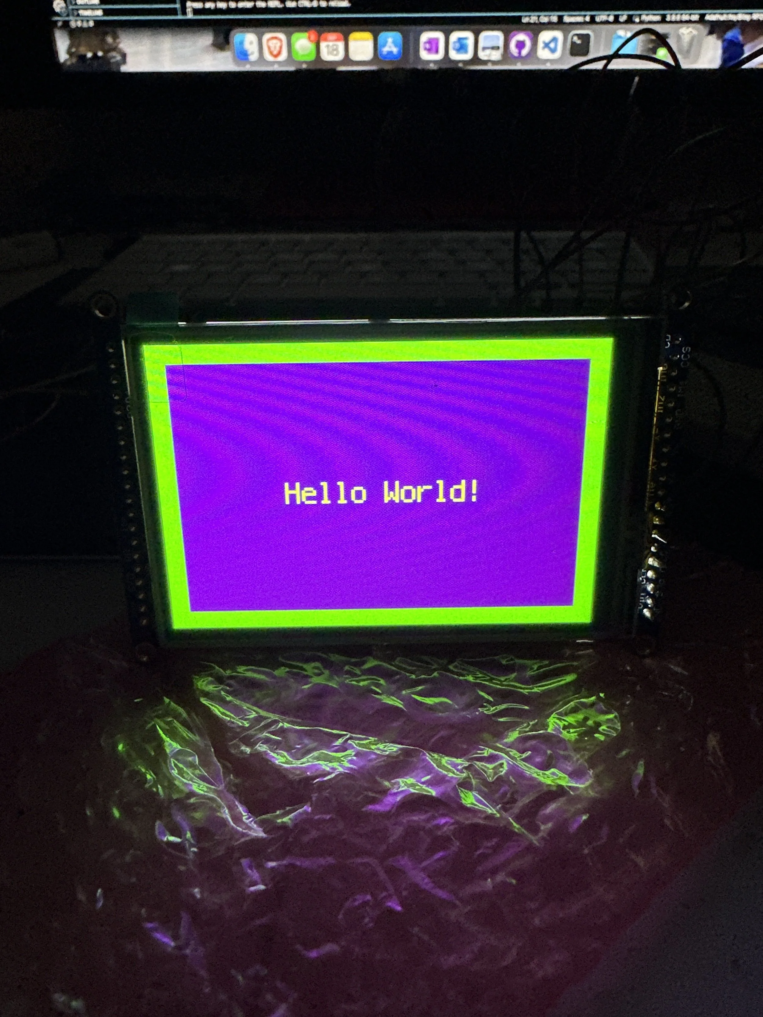
It’s important to test components and make sure everything works as expected. To keep development simple, the displayio library was used. It is not quite as performant as stage and does not (as of this writing in 2024) provide any built-in functions for rotating bitmaps. The display used in this example is connected via SPI, but this could be improved to used an 8-Wire. Later examples will show the slowness of the display, on account of using SPI among other factors. The Hello World example can be found here.
It’s untrue to say no one asked for this - My friend wanted to gift his wife a custom trinket symbolizing his love “to the moon and back” for her. We met up and quickly sketched out an idea to work with, based on something like this example from Adafruit. A trip to the local Microcenter and several stops around to find an elusive CR1220 coin battery later, and I was off to the races building out the software.
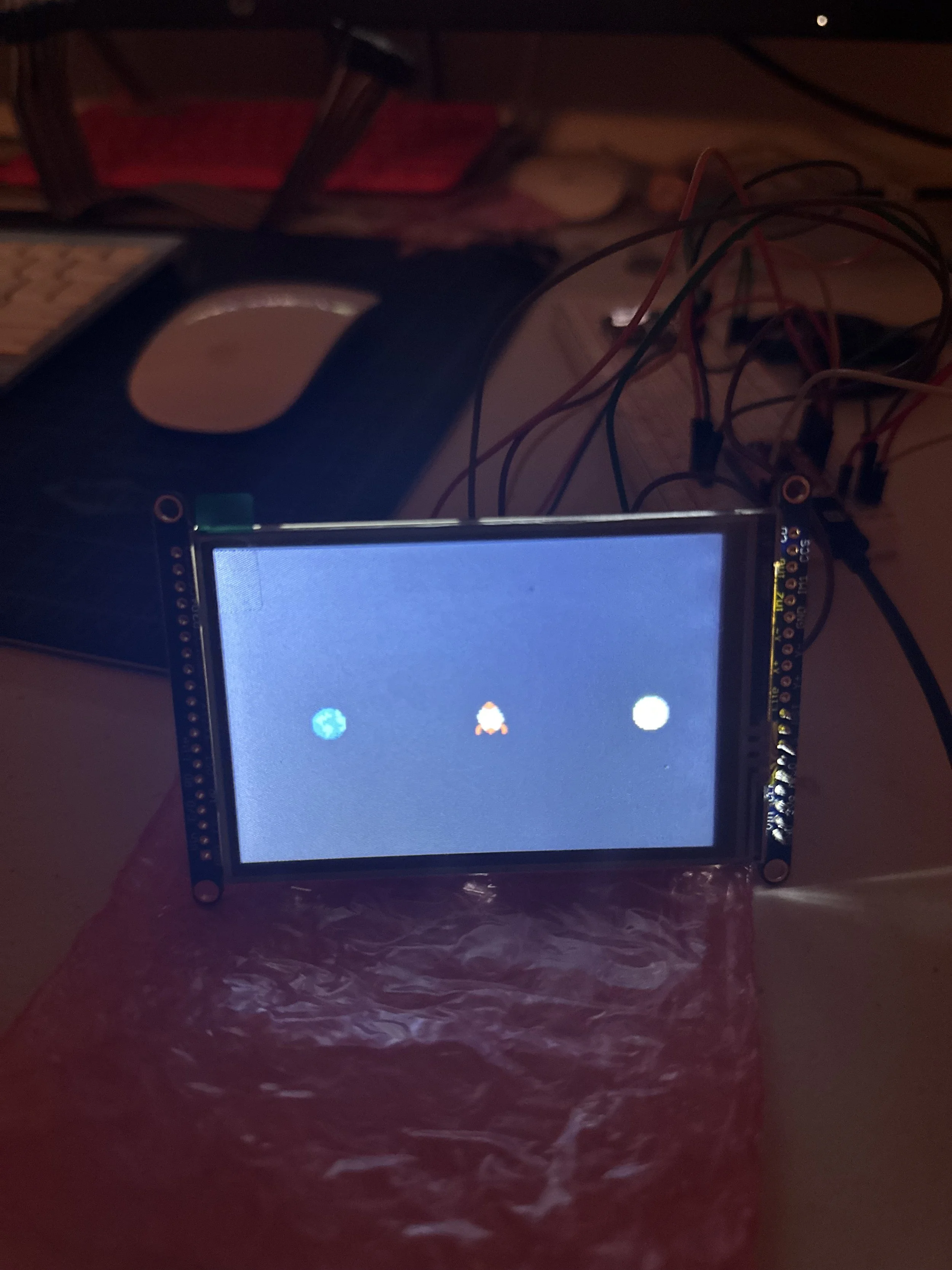
Open source is amazing for many reasons, one of my favorite is how quickly it move projects along when utilized correctly. The sprite sheet is based off Peony’s “Space” Pixel art. Only the Earth, Moon, and Rocket sprites were used here. The sprite sheet was optimized to have a more limited color palette, and cut up for easier manipulation with Adafruit’s ImageLoad library. In this workflow, it is necessary to create an indexed bitmap, and to take note of which colors are in which position. It is up to the programmer to specify the alpha color in displayio.
Putting it all together
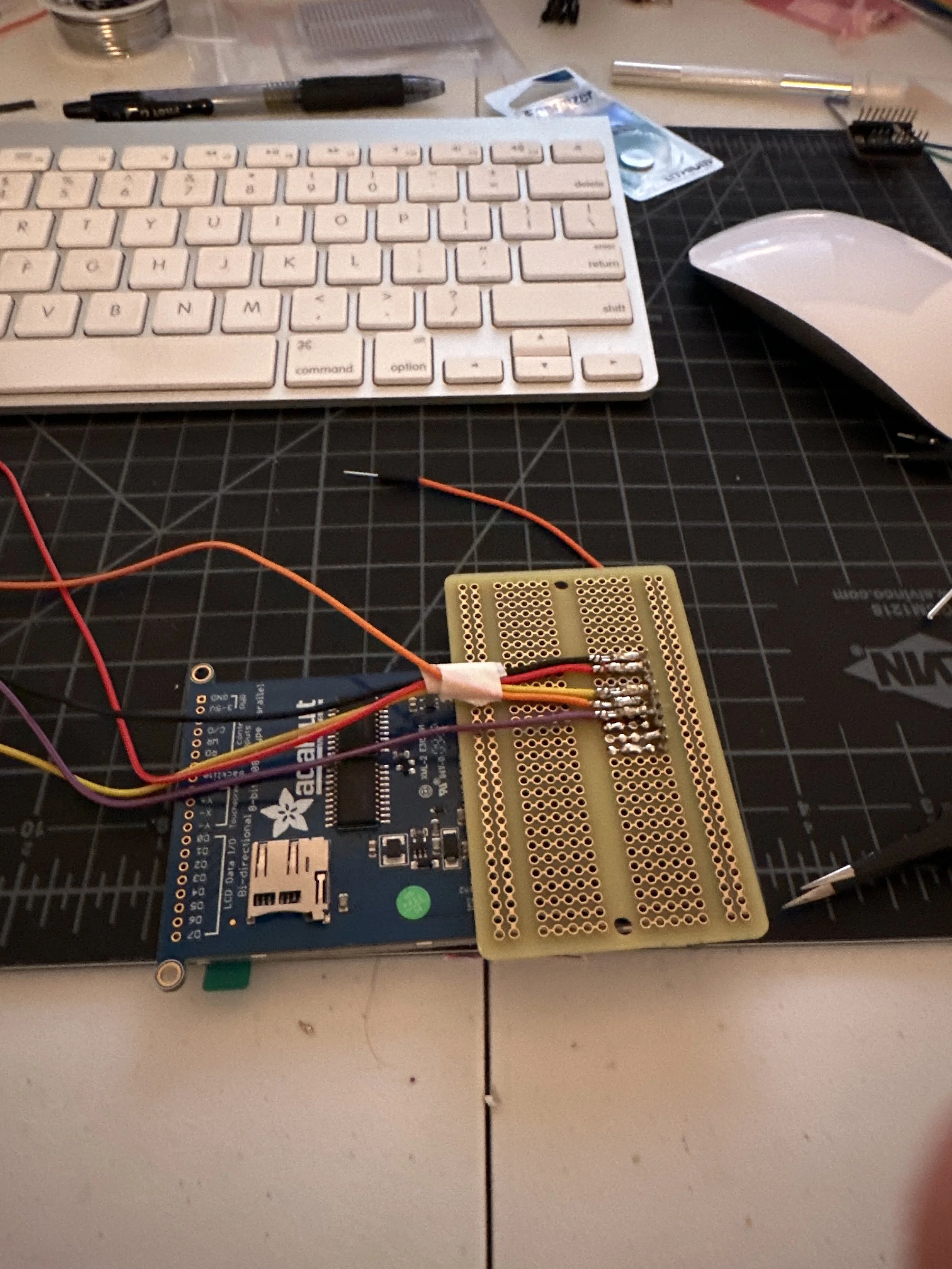
Assembling the board was a bit of a bear. A one-off project can make PCB design quite expensive, but it was almost worth doing so. There are 3 main components to connect; In this photo the screen is being soldered to its own board.
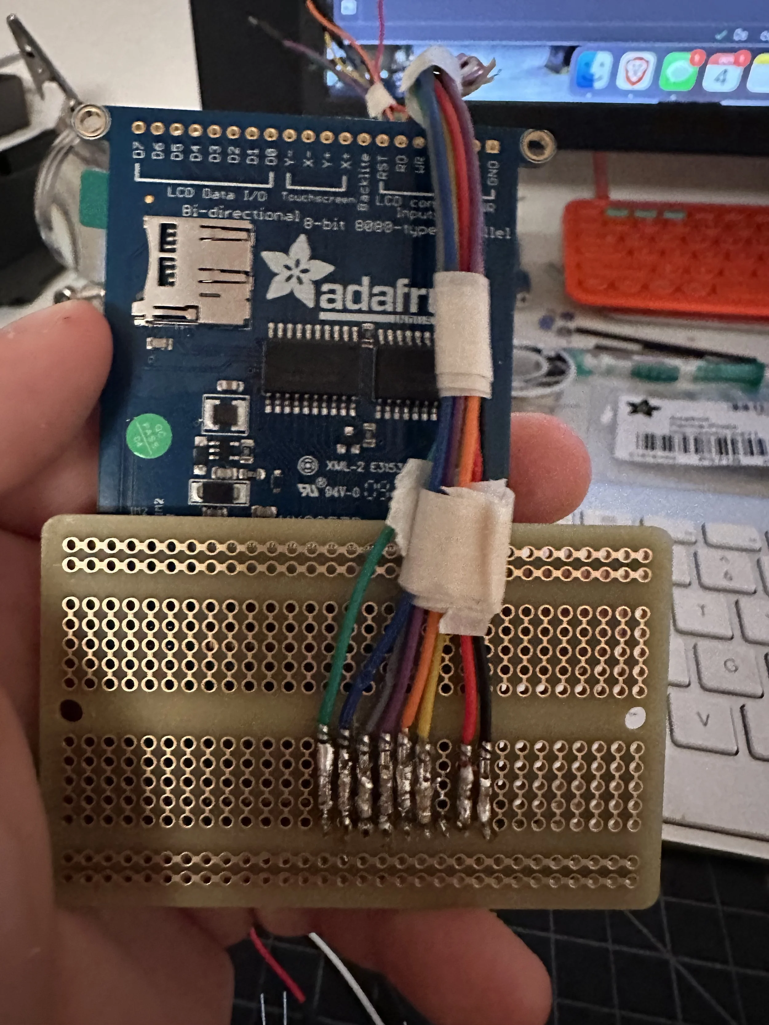
The SPI interface in this case requires 8 connections: 5V, GND, MISO, MOSI, CLK, C/S, DC, Backlight. The screen was connected to a PCB Proto board with headers, and wires were soldered on from there. This image is the completed screen sub-assembly.

The mainboard assembly hosts the microcontroller and real-time-clock. The RTC allows for keeping time should the device lose power. The idea is the microcontroller will write a timestamp with the number of cycles passed, then read this timestamp and calculate the difference with current time.

The final assembly with screen attached to mainboard. The screen was affixed to the mainboard with headers soldered to the board but unconnected. Everything is more or less held with draft tape while soldering happens.
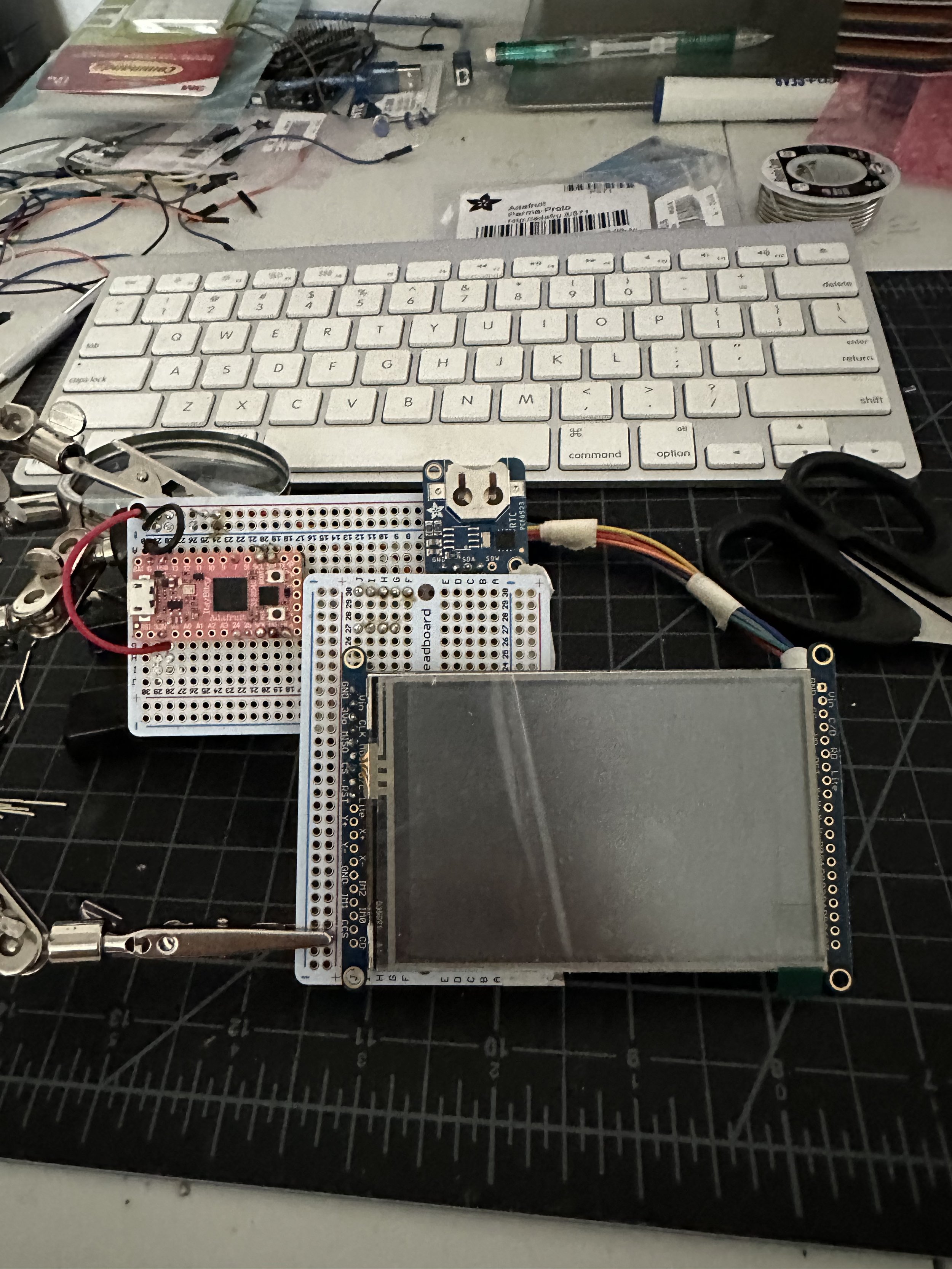
Final assembly with everything connected! It is not so straight, and more time should have been spent investigating build methods - The uneven construction introduced headaches with the case design process.
Making the animation
The particle simulation is very simple. Within a system, there are an arbitrary number of particles that are initialized as an array. Each particle has an initial x,y position, previous x,y position, and x,y velocity. When initialized, the programmer will specify the size (in pixels) of the simulation, the speed (in x and y axises), the number of particles, and whether or not to spawn particles randomly along each axis. A random range function can be used to randomize velocity, and everything gets wrapped up inside its own TileGrid. There is no collision detection, and at this time particles do not have a color attribute. This animation moves like jelly; the GIF shown here is sped up 5x! There are surely ways to optimize the drawing, but that is task outside the scope of this project’s timeframe!
Animating the ship sprite was very simple, and while rotation was explored to create a more interesting visual, that was not something I was able to implement when working on this project. The animation is simply moving the sprite so many units along the x-axis, flipping it, and then moving it the same number of units back. A simple sine wave!
Some of this stuff is quite difficult….
Working with the RTC was the most difficult aspect of this project, second to rotation. With the latter, I could at least forgo it and stick with displayio’s native functions that can transpose and flip the xy direction of images. Had I worked with it more, I could have gotten beyond a simple 180 turn when the rocket needs to spin around.
Connecting to the RTC and pinging it for a timestamp is relatively easy, but in the context of this project a counter is being built. We need to know when light has traveled from the earth to the moon and back so we can increment our counter. We can create a background process and periodically check in to see if we need to increment, or we can take advantage of interrupts and set the timer chip to signal an interrupt at certain intervals. The latter means we only tell the microcontroller to increment when it receives an interrupt signal from the RTC.
Thankfully Adafruit maintains libraries for the RTC chips available for purchase, but they are not always included in the CircuitPython installed on board purchased, as was the case here. Be sure to check your modules to include the necessary components. I made a mistake in the procurement process that led to purchasing an RTC chip whose alarm will only fire on complete minutes, which is far too slow for the project requirements. Going this route was not something I wanted to get too hung up on, as I did want this project completed.
Instead, asyncio was used set up a “background task” that checks the RTC before updating the display, and if the cycle completed (~3 seconds) then the counter is incremented.
The Recipe:
Electronic Components and tools:
All Electronic parts purchased at Microcenter, but should also be available from Adafruit or another electronic parts retailer.
A case for the project - Fun idea for a 3D Print or Paper Mache!
Display (Compatible with chosen board, SPI or Parallel)
A real time clock module (Any with an I2C interface should be fine)